


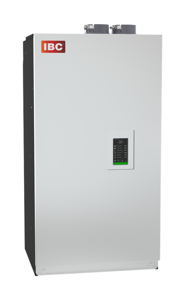
CX 150
CX 199
Residential High Efficiency Combi Condensing Boiler
A Unique balance of Performance, Efficiency and Value for all your home heating and DHW needs.


Features
Technical Data
Connections
Documentation
Features
| NEW V-10 CONTROL INTERFACE |
| Express Setup – Program your boiler in seconds |
| Remote Monitoring & Diagnostics |
| Easy USB programmability |
| Instant Visibility – Built-in warnings on the controller |
| Real-time monitoring of DHW temperature |
| Intuitive Alert System with detailed error messages |
| Visible flame current data for troubleshooting |
| Load combining |
| Cascade up to 4 units. |
| MAXIMUM PERFORMANCE |
| 95% A.F.U.E. – Reduce operating costs and heat your home faster. |
| Full boiler capacity available for both |
| DHW and space heating |
| State-of-the-art, ASME, 439 grade, SS firetube HX |
| Brazed plate HX for DHW production |
| Turndown ratio 10:1 means you have the power to heat your home during the coldest weather, yet reduce short cycling when the weather is mild. |
| North American built. All CXTM models are designed, engineered and assembled in Canada |
| MORE BUILT-IN FEATURES |
| Built-in 4 zone pump or valve control |
| In addition to the primary control – 5 pumps total |
| Replaces the need for external zone control. |
| Built-in factory wired primary pump. |
| Built-in combi block for DHW supply and ease of service from front of unit |
| MFZ Technology: Patented moisture management system. Protects and ensures long life for all boiler components |
| Built-in outdoor reset control of water temperature |
| Built-in CSA/UL approved low water cut-off and manual reset high limit. |
| EASY TO INSTALL AND SERVICE |
| Universal parts. With only one fan and one controller, servicing all CXTM models just got a lot easier. |
| All combi block components can be easily replaced individually. |
| PVC/CPVC/PPs approved. |
| Vent lengths up to 50 ft. with 2” and 170 ft. with 3” |
| Easy to inspect HX featuring a condensate draining system that cleans as it heats |
Technical Data
| SPECIFICATIONS | CX 150 | CX 199 |
| CSA Input (Nat. Gas or Propane) – MBH | 15-150 | 20-199 |
| CSA Input (Nat. Gas or Propane) – kW | 4.4-44 | 5.9-58.3 |
| CSA Output – MBH | 14.3-138.5 | 19.1-183.7 |
| CSA Output – kW | 4.2-40.6 | 5.6-53.8 |
| DHW – CSA Input (Nat. Gas or Propane) – MBH | 15-150 | 20-199 |
| DHW – CSA Input (Nat. Gas or Propane) – kW | 4.4-44 | 5.9-58.3 |
| A.F.U.E. | 95% | 95% |
| Min. Gas Supply Pressure (Nat. Gas or Propane) – Inch w.c. | 4 | 4 |
| Max. Gas Supply Pressure (Nat. Gas or Propane) – Inch w.c. | 14 | 14 |
| Ambient Temperature – Low | 32°F/0°C | 32°F/0°C |
| Ambient Temperature – High | 122°F/50°C | 122°F/50°C |
| Max. Relative Humidity (Non-Condensing) | 90% | 90% |
| Min. Water Temperature | 34°F/1°C | 34°F/1°C |
| Max. Water Temperature (Electronic Hi-Limit) | 190°F/88°C | 190°F/88°C |
| Max. ΔT – Supply/Return (Electronic Fence) | 40°F/22.2°C | 40°F/22.2°C |
| Max. Water Temperature Lockout Limit | 201°F/94°C | 201°F/94°C |
| Power Use (120 Vac/60 Hz) @ Full Fire – Watts (with pump) | 94.8 | 106.9 |
| Weight (Empty) – lbs/Kg | 100/45.4 | 113/51.3 |
| Pressure Vessel Water Content – USG/Liters | 2.79/10.56 | 3.51/13.29 |
| Max. Boiler Flow Rate – US gpm | 19 | 25 |
| Min. Boiler Flow Rate – US gpm | 3 | 4 |
| Max. Boiler Operating Water Pressure* – psig | 50 | 50 |
| Min. Boiler Water Pressure – psig | 8 | 8 |
| Max. DHW Water Pressure – psig | 150 | 150 |
| Min. DHW Water Pressure – psig | 40 | 40 |
| Relief Valve Pressure (Supplied) – psig | 30 | 30 |
| Approved Installation Altitude – ASL | 0-12,000’ | 0-12,000’ |
| Venting 2” | 50’ | N/A |
Venting 3” DHW Delivery at 70’F / 39’C Temp Rise – US gpm | 170′ 4.1 | 100′ 5.5 |
Connections
| PIPING CONNECTIONS | ||
| Description | CX 150 | CX 199 |
| Flue Outlet | 3” PVC/CPVC or PPs (80mm) | 3” PVC/CPVC or PPs (80mm) |
| Combustion Air Inlet | 3” PVC/CPVC or PPs (80mm) | 3” PVC/CPVC or PPs (80mm) |
| Return Water Inlet (Tepid) | 1” NPT-M | 1” NPT-M |
| Supply Water Outlet (Hot) | 1” NPT-M | 1” NPT-M |
| Condensate Outlet | 3/4” Hose | 3/4” Hose |
| Gas Inlet | 1/2” NPT-F | 1/2” NPT-F |
| DHW Outlet (Hot Water) | 3/4” NPT-M | 3/4” NPT-M |
| DHW Inlet (Cold Water) | 3/4” NPT-M | 3/4” NPT-M |
| VENTING MAXIMUM EQUIVALENT LENGTHS | ||
| Sched. 40; Rigid PPs | CX 150 | CX 199 |
| 2” | 50’ (max.) | Not Permitted |
| 3” | 170’ (max.) | 150’ (max.) |
| 90° Vent Elbow | Allow 8’ for each 90° elbow | Allow 8’ for each 90° elbow |
| 90° Long Sweep Elbow | Allow 5’ for each 90° elbow | Allow 5’ for each 90° elbow |
| 45° Elbow | Allow 3’ for each 45° elbow | Allow 3’ for each 45° elbow |
| PPs 87-90° Elbows | Allow 8’ for each 87-90° elbow | Allow 8’ for each 87-90° elbow |
| 2” SS Sidewall Terminal | Not Permitted | Not Permitted |
| 3” SS Sidewall Terminal – Exhaust Vent | Allow 20’ | Allow 20’ |
| 3” SS Sidewall Terminal – Air Intake | No Allowance Required | No Allowance Required |
| Flexible PPs 3” Flexible | Limited to 45’ (max.) | Limited to 30’ (max.) |
| CLEARANCE FROM BOILER CABINET | ||
| Surface | Min. Distance From Combustible Surfaces | Recommended Distance For Installation and Service |
| Front | 2″ | 24″ |
| Rear Flue Connection | 0″ | 0″ |
| Left Side | 0” | 4” (allow access to water connections) |
| Right Side | 1″ | 4” (allow access to water connections) |
| Top 2” | 2″ | 6″ (for vent connection) |
| Bottom | 0″ | 12” (for condensate trap and piping) |
Documentation